Glossary of Resistor Terminology
Absolute Tolerance:
The tolerance of a resistor or a specific resistor in a network is also called the absolute tolerance.
Absolute TCR:
The Temperature Coefficient of Resistance (TCR) of a resistor or a specific resistor in a network is also called the absolute TCR.
Temperature Coefficient of Resistance (TCR):
Typical Temperature Coefficient of Resistance (TCR)
The Temperature Coefficient of Resistance (TCR) is expressed as the change in resistance in ppm (0.0001%) with each degree of change in temperature Celsius (°C).
For example, a resistor with a TCR of +100 ppm/°C will change +0.1% total over a 10-degree change and +1% total over a 100-degree change.
The TCR value quoted on specification sheets is typically quoted as being referenced at +25°C and is the +25°C to +75°C slope of the TCR curve.
TCR is typically not linear, but parabolic with temperature, as illustrated by the accompanying fig-1. Often the circuit designer treats the TCR as being linear unless very accurate measurements are needed.
MIL STD 202 Method 304 is often referenced as a standard for measuring TCR. The following formula expresses the rate of change in resistance value per 1 °C in a prescribed temperature range:
- TCR (ppm/°C) = (R - Ro) / Ro × 1 / (T - To) × 106
- R: Measured resistance (Ω) at T °C; Ro: Measured resistance (Ω) at To °C
- T: Measured test temperature (°C); To: Measured test temperature (°C)
In the context of a resistor network, this TCR value is called the absolute TCR in that it defines the TRC of a specific resistor element.
Voltage Coefficient of Resistance (VCR):
The Voltage Coefficient is the change in resistance with applied voltage. This is entirely different and in addition to the effects of self-heating when power is applied.
A resistor with a VCR of 100 ppm/V will change 0.1% over a 10 Volt change and 1% over a 100 Volt change. The rate of change in resistance value per 1 Volt in the prescribed voltage range is expressed by the following formula:
- VCR (ppm/V) = (Ro - R) / Ro × 1 / ( Vo - V) × 106
- R: Measured resistance (Ω) at base voltage; V: Base voltage
- Ro: Measured resistance (Ω) at upper voltage; Vo: Upper voltage
Maximum Working Voltage:
The maximum voltage applied continuously to a resistor or a resistor element. The maximum value of the applicable voltage is the rated voltage at the critical resistance value or lower.
If the circuit designs permits, the choice of a high ohmic value resistor or divider network will improve the resistor′s performance because it will operate at lower power.
Power Rating:
Power ratings are based on physical size, allowable change in resistance over life, thermal conductivity of materials, insulating and resistive materials, and ambient operating conditions.
For best results, employ the largest physical size resistors at the less than their maximum rated temperature and power. Never use them continuously at their maximum rating unless you are prepared to accept the maximum allowed life cycle changes.
If the circuit designs permits, the choice of a high ohmic value resistor or divider network will minimize the power level and improve the resistor′s performance as it is operating at a lower power level. See the Derating curve entry in this glossary.
Rated Power:
Rated power is the maximum value of power (watts), which can be continuously applied to a resistor at a rated ambient temperature. The basic mathematical relationship is Equation: Power (Watts) = (Current (Amps))2 × Resistance (Ohm).
If the circuit designs permits, the choice of a high ohmic value resistor or divider network will minimize the power level and improve the resistor′s performance because it is operating at a lower power and temperature level.
Rated Voltage:
The maximum voltage applied continuously to a resistor at the rated ambient temperature. Rated voltage is calculated from the following formula, but it must not exceed the maximum working voltage. Equation: Rated Voltage (V) = (Rated Power (W) × Nominal Resistance Value (Ω))1/2
High voltage resistors often are potted or operated in oil as the arc over voltage, in air, is approximately 10,000 volts per inch. Ohmcraft′s resistors feature higher voltage ratings due to their high square count and associated design characteristics.
Derating Curve:
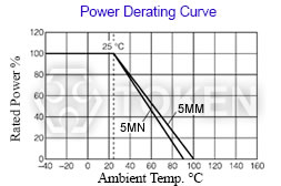
Typical Derating Curve
The curve that describes the relationship between the resistors′s operating temperature and the maximum value of continuous power permitted at that temperature.
If the circuit designs permits, the choice of a high ohmic value resistor or divider network will minimize this consideration and improve the resistor's performance because it will operate at lower power.
Nominal Resistance:
The adjective nominal (ultimately from Latin means "name") generally relates to the concept of names, and often to the difference between what something is in name (ideally or theoretically) and what it is in reality. Thus it may refer to: a value that is used as the name for an actual value of resistance which is close but not exactly the same.
Dielectric Withstanding Voltage:
The rated voltage that can be applied to a designated point between the resistive element and the outer coating, or the resistive element and the mounting surface, without causing dielectric breakdown.
Noise:
Noise is an unwanted AC signal from within the resistor. Resistive noise can have a devastating effect on low-level signals, charge amplifiers, high gain amplifiers, and other applications sensitive to noise. The best approach is to use resistor types with low or minimal noise in applications that are sensitive to noise.
Design Guide for High Precision Resistors
Introduction:
Even in this digital age, a number of measurement and instrumentation applications rely on the accuracy of the value of one or more resistors.
To guarantee the performance of the system, the designer must understand what factors can affect the value of a precision device, and how the combined effect of these factors may be evaluated.
There are essentially three types of error source to be understood.
- The first is measurement errors, which limit the precision with which the actual resistance value can be known.
- Secondly, short-term change factors, reflecting uncertainty in the resistance value in a customer′s recently assembled PCB.
- Thirdly, long-term change factors, reflecting value drift throughout the product′s life.
The combination of all these factors is termed total excursion.
Measurement Errors:
Care is often needed when measuring precision devices to keep the measurement uncertainty at a negligible level compared to the resistance error. In addition to controlling the measurement temperature and voltage, the connections may need to be four-terminal (Kelvin) and using screened cables. If very high values are encountered, the use of guarding techniques may be needed to eliminate surface leakage paths.
The instrument used must have sufficient resolution and traceable calibration to enable the measurement uncertainty to be quantified. If measurement uncertainty cannot be made negligible, it should be allowed for. For example, when checking the value of 0.01% tolerance resistor on a meter with 0.001% (10ppm) measurement uncertainty, acceptance limits of 0.009% should be used.
Short-Term Change Factors:
The most basic factors are tolerance and temperature coefficient of resistance (TCR).
The tolerance is simply the maximum percentage deviation of actual resistance value from nominal for resistors as delivered, measured at a specified temperature (normally 25°C). In some cases the measurement voltage is also specified.
The TCR specifies a limit on the variation of resistance with temperature. It is defined as the maximum average change in resistance value per degree centigrade between two defined temperatures, and expressed in ppm/°C. Unless otherwise stated, the tolerance and TCR figures are positive or negative, ie, "0.1%" means "±0.1%".
When defining the temperature range for a resistor it is necessary to consider the internal ambient temperature, the effect of nearby heat-generating components and the temperature rise due to dissipation in the resistor itself.
There are other factors that can affect resistance value measurements in some cases. For high-value and high-voltage parts, the value obtained can depend on the measurement voltage used. The maximum error from this source may be calculated from the voltage coefficient of resistance (VCR), which expresses this change in ppm/V. VCR is always negative. Customers may specify measurement voltages which reflect actual operating conditions to eliminate this error.
At the other extreme, very low-value resistors for current-sensing applications may generate thermal EMFs at junctions of dissimilar metals when a temperature difference arises through self-heating, or some other cause. This can be significant compared to the resistive volt drop and therefore generate an error. Designing for thermal symmetry across the resistor can normally eliminate this error source.
TCR and VCR both produce reversible changes in resistance value; the resistance would recover to its original value if measured at room temperature and standard measurement voltage. Other changes are permanent, and the first of these to consider is value shifts due to processing by the PCB assembler. This can be assessed by looking at the performance figure for resistance to solder heat in the datasheet.
Long-Term Change Factors:
Datasheets often quote a number of figures for the performance data to enable the designer to assess the maximum lifetime change in resistance value. In general, only one of these figures should be used – the one that most closely reflects operating conditions.
The shelf life figure applies where loading is negligible and the environment is benign. The load figure applies where power dissipation is the main factor, the long-term damp heat figure where humid environments may be encountered.
In all these tests the majority of the value change happens within the period of the test, as the value will tend to stabilize. For example, the 1,000-hour load figure is a good guide to the change predicted over a longer period of service. For greater precision, mathematical models exist to extrapolate from tested stability levels to long-term stability under application conditions.
Clearly initial calibration can be used to eliminate tolerance and soldering process induced errors.
General Information of Ultra Precision Resistors
High Precision Devices Made in DeMint:
DeMint is equipped to design and produce custom components to meet many design and reliability demands.
DeMint's line of high-reliability and precision products reflects a long-term commitment to our industrial and military customers. In addition to standard industy-grade resistor products, we also have many resistive products designed to meet various military source-controlled drawings.
We continually strive to meet the changing application requirements of the markets by developing new products and manufacturing technologies on an on-going basis.
Enhanced Precision and Stability for Low-Cost Uses:
Every component DeMint provides to the commercial, industrial, and military markets for cost-efficiency uses is backed by the comprehensive testing and failure analysis capabilities of our own technical staff, whom are industrial experts in understanding and meeting the requirements of the environment.
Low TCR - Fast Approach to A Steady State:
DeMint Electronics provides a precision Temperature Coefficient of Resistance TCR as low as 2 ppm/°C, If you must guarantee a smaller resistance change in your application. TCR is the best known parameter used to specify a resistor′s stability, and is used to depict the resistive element′s sensitivity to temperature change due to ambient temperature variations.
A resistor's TCR tells how much its value changes as its temperature changes. It is usually expressed in ppm/°C (parts per million per degree Centigrade) units.
Long-Term Proven Service:
Our technical expertise, our knowledge of the industry, our broad product offering, and our ability to work long-term are all part of DeMint′s ongoing commitment to meeting the changing requirements of our most reliability-conscious customer, today and in the future.
Precision Resistor Design Notes and Catalogue Download: